Hi, my name is Tony – I’ve an acquired brain injury from a car accident in 2004. The injury limited my ability to cope with mental load so spent a lot of time at home, in the quiet with low lighting and limited thinking. A friend suggested fishing, quiet, solo, could be done any time… A perfect sport !
Eventually I purchased a boat, needed to get it from the garage to the tow bar of the car and so began the learning process to find a way to do what i wanted to do.
In a nut shell – I reverse engineered my home power wheelchair, as I had only one power chair at that time.
Arduino is used to accept the inputs you choose.
– A start up pulse is sent via the MAXIM DG419
– Arduino outputs to a MAX485 transceiver chip
– MAX485 converts the software serial into an RS485 protocol the Power Module uses
A mobility shop was throwing away an old power wheelchair and I now use this. I tried a few boat styles, unfortunately mobility still being an issue I ended up going for a kayak that now uses a Bixby Jet inboard electric motor and a Hobie Power Pole electric anchor. I drive the kayak to the boat ramp have a fish and then drive the RC unit back to the garage, ready for when i get home…hopefully with a boat load of squid !
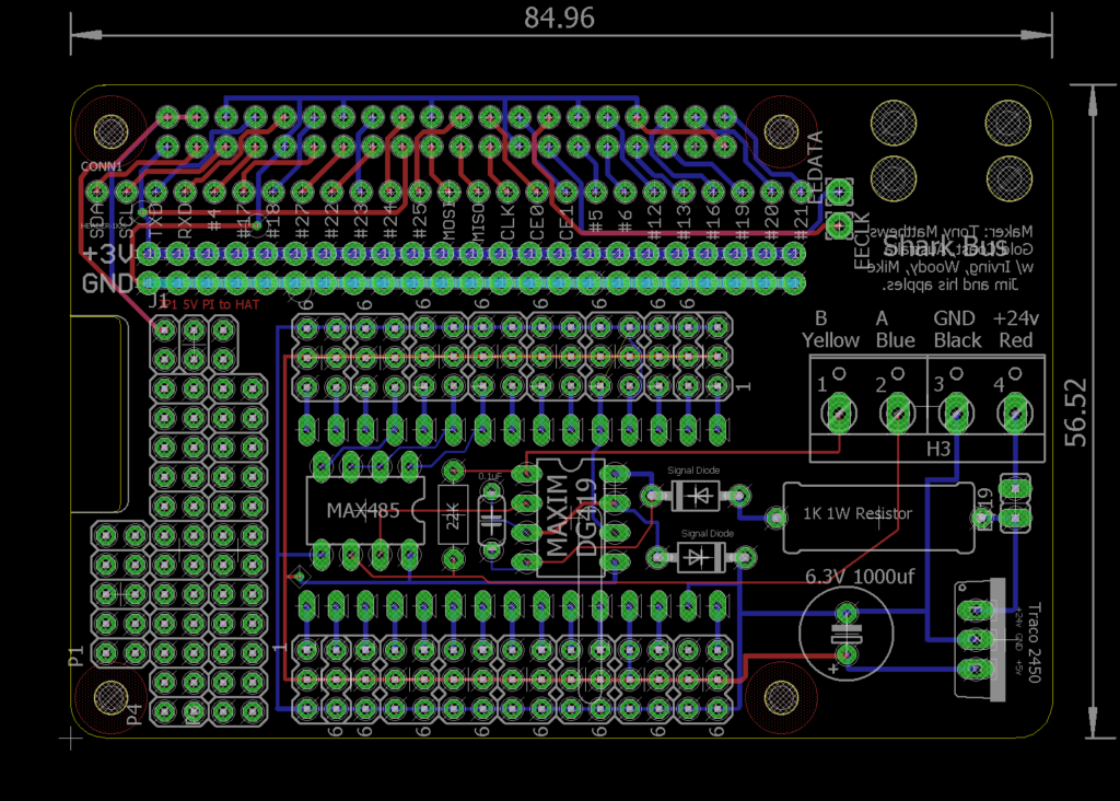


Arduino based RC module for the Dynamic Shark range of Power Wheelchair controllers
Use with any input you choose : Analog Joystick, RC receiver, Corded Nintendo Wii or Remote Wii.
or… Stack with a Raspberry Pi B+ , let the Arduino communicate with the Power module
add sensors : IR, Ultrasonic, GPS, Altimeter, Accelerometer or ….. even remove the Arduino and let the Pi do all of the dirty work. Programming is with the Arduino IDE.
Designed by Tony Matthews with coding assistance from Wheelchairdriver.com members
Woody, Lenny, Doung L, Sir Mike and Jim from the UK
These boards are available directly from Dirty PCB or by post till i run out.
https://dirtypcbs.com/store/designer/details/11063/5125/nano-shark-hat-v3-23-zip
In my builds i have used a TRACO POWER 2450 power regulator as in one version i used the one regulator to provide power to the Arduino Shark Emulator and a Nintendo Wii 2.4gHz wireless receiver.
I started out with a 7805 Voltage Regulator but was getting brown outs on the Wii. It got REALLY hot with out a heat sink. The 2450’s are much more efficient and cope with the wider voltage ranges that occur if you are running this from 24v solar panels.
The same holds for the MAXIM DG419, other brands of DG419 (that i looked at) would not handle the voltages from a fully charged 24v Lead Acid battery pack.
Below is my Code for the project, its open source but you may need to update your libraries and the code that calls the old ones at the beginning of the sketch.
// This sketch is to emulate the packet of data that the Shark Joystick sends
/
Author: Tony Matthews ammatthews at gmail dot com
BitMath coding by – ‘Irving’
Building on work by Jim with his RoboBoard + sensor wheelchair.
License: FreeBSD
THIS CODE IS MISSING THE LIBRARIES – you will need to download, install and insert your own code.
/
/
Copyright (c) 2015, Tony Matthews
All rights reserved.
Redistribution and use in source and binary forms, with or without
modification, are permitted provided that the following conditions are met:
- Redistributions of source code must retain the above copyright notice, this
list of conditions and the following disclaimer. - Redistributions in binary form must reproduce the above copyright notice,
this list of conditions and the following disclaimer in the documentation
and/or other materials provided with the distribution. THIS SOFTWARE IS PROVIDED BY THE COPYRIGHT HOLDERS AND CONTRIBUTORS “AS IS” AND
ANY EXPRESS OR IMPLIED WARRANTIES, INCLUDING, BUT NOT LIMITED TO, THE IMPLIED
WARRANTIES OF MERCHANTABILITY AND FITNESS FOR A PARTICULAR PURPOSE ARE
DISCLAIMED. IN NO EVENT SHALL THE COPYRIGHT OWNER OR CONTRIBUTORS BE LIABLE FOR
ANY DIRECT, INDIRECT, INCIDENTAL, SPECIAL, EXEMPLARY, OR CONSEQUENTIAL DAMAGES
(INCLUDING, BUT NOT LIMITED TO, PROCUREMENT OF SUBSTITUTE GOODS OR SERVICES;
LOSS OF USE, DATA, OR PROFITS; OR BUSINESS INTERRUPTION) HOWEVER CAUSED AND
ON ANY THEORY OF LIABILITY, WHETHER IN CONTRACT, STRICT LIABILITY, OR TORT
(INCLUDING NEGLIGENCE OR OTHERWISE) ARISING IN ANY WAY OUT OF THE USE OF THIS
SOFTWARE, EVEN IF ADVISED OF THE POSSIBILITY OF SUCH DAMAGE. The views and conclusions contained in the software and documentation are those
of the authors and should not be interpreted as representing official policies,
either expressed or implied, of the FreeBSD Project.
*/
// This code is incomplete and still under revision.
// Its also got junk that may not be needed,
const int onOffPin = 2; // Digital Pin for software on/off button
// Pin outs for RS485 chip
const int roPin = 7; // to RO of Max485 to RX of Arduino
const int dePin = 9; // to DE and RE of Max485
const int diPin = 10; // to DI of Max485 to TX of Arduino
// Pins for PnP/NpN data switch, between data and 15-24v start pulse.
const int dataSwitch = 6; // Digital swtich for DG419
// Led Indicator monitor
const int led = 13;
//Boolean name holder for current state.
boolean onOffstate = LOW;
// Analog input pins assignments
word speedPot = A1; // Speed Pot input value
word directionPot = A2; // Direction Pot input value
// Names for analogRead values of Analog Pots
word speedPotVal;
word directionPotVal;
// Names for Mapped analogRead Values of Pots
word speedPotValMapped;
word directionPotValMapped;
// Integers for Irvings code
unsigned char maxSpeed; // unsigned char, same as byte (8 bit) – unsigned number from 0-255
word speed; // int (16 bit) – signed number from -32768 to 32767
word direction; // int (16 bit) – signed number from -32768 to 32767
// data packet
unsigned char data[12];
unsigned long timer = 0;
SoftwareSerial sharkSerial (roPin, diPin, false); // ‘true’ sets this to invert software serial output.
void setup() {
sharkSerial.begin(38400);
delay(300);
pinMode(led, OUTPUT); // Arduino led to monitor on or off state.
pinMode(onOffPin, INPUT_PULLUP); // Software on/off button, turn on internal pull up resistors.
pinMode(dataSwitch, OUTPUT); // Set Data switch pin to Output
digitalWrite(dataSwitch, LOW); //Start Data in LOW = data connected to bus, High=15-24v connected to bus
digitalWrite(dePin, LOW);
}
void loop() {
// Starts in SOFTWARE Off state from physical power on.
// Code to monitor ‘Software’ on/off button ‘onOffPin’
// Check state, if “on” , “turn off”
if (digitalRead(onOffPin) == LOW && onOffstate == HIGH)
{
onOffstate = !onOffstate; //toggles onOffstate from HIGH to LOW (if it was HIGH when the on/off button is pressed)
digitalWrite(dePin, LOW); // Puts Max485 into recieve mode
digitalWrite(led, onOffstate); // Turn off the LED on arduino as indication of state
delay (300);
}
// If ‘off’ turn ‘on’
// check state, if on/off button is pressed, change state to “ON” and run start up sequence.
else if (digitalRead(onOffPin) == LOW && onOffstate == LOW)
{
onOffstate = !onOffstate; // toggle state to HIGH if in’off mode’ and on/off button is pressed
digitalWrite(led, onOffstate); // turn on LED pin to get visual indication of on/off state
digitalWrite(dePin, HIGH); // Hold dePin high when transmitting.
delay(100);
sharkStartup(); // call function sharkStartup()
delay(15);
}
if (onOffstate == HIGH )
{
digitalWrite(led, onOffstate); //Keep arduino LED ‘on’ as indication of mode arduino is in
digitalWrite(dePin, HIGH); //Keep dePin to high for transmit mode.
sharkOnMode();
}
}
// my Dynamic Shark start up sequence, other joysticks will have different start up packets.
void sharkStartup () {
{
digitalWrite(dataSwitch, HIGH); // Flip data switch, HIGH = PNP ‘Off’, NPN ‘ON’
delay(298);
digitalWrite(dataSwitch, LOW); // Flip dats switch, LOW = PNP ‘On’, NPN ‘Off’
delay(10);
}
{
/*build start up packet
I’ve yet to put the factory notes in here but it will change for each emulator as its just
the date of manufacture and such boring stuff…
*/
data[0] = (0x74);   //
data[1] = (130);    //
data[2] = (133);    //
data[3] = (130);    //
data[4] = (128);    //
data[5] = (136);    //
data[6] = (205);    //
data[7] = (160);    //
data[8] = (128);    //
byte sum = 0;
for (int i = 0; i < 9; i++)
  sum += data[i] & 0x7f;    // 0x7f is same a ;s 0b01111111 but easier to write/check
data[9] = 0x7f - sum;       //Checksum  OK = (141)
data[10] = (15);      // all packets end with this identifier

for (unsigned char i = 0; i < 11; i++)
  sharkSerial.write(data[i]);
}
}
void sharkOnMode() {
{
digitalWrite(dePin, HIGH); // set MAX485 to High = TX active.
speedPotVal = analogRead(speedPot);
{
  if (speedPotVal >= 1023)
    speedPotVal = 1023;

  if (speedPotVal <= 1)
    speedPotVal = 1;
}

speed = map(speedPotVal, 0, 1024, 1, 1023 );


directionPotVal = analogRead(directionPot);
{
  if (directionPotVal >= 1023)
    directionPotVal = 1023;

  if (directionPotVal <= 1)
    directionPotVal = 1;
}
direction = map(directionPotVal, 0, 1024, 1, 1023);
}
{
/* Following are notes on Shark Remote data Byte information packets (what each byte holds data for)
Type 00 SR General Information
This packet contains the joystick speed and direction ( 10 bit readings), speed pot setting (8 bit reading), and input and status
bits.
The minimum allowable length for this packet is 6 data bytes.
If the SPM receives only bytes 0-5, and the checksum is correct, the SPM shall assume that it is operating with a previous
version of the Shark Remote and take the following actions:
Disregard the Operating Mode in byte 5
Disable all lighting and actuator functionality.
Note that these actions shall be taken regardless of whether the SR indicated in its power-up packet that it has lighting and/or
actuator functionality.
*/
/* Build "shark remote" data serial packet or in this case the emulator data packet
     Interpretation will be slotted in here for sensors added to the power chairs
*/
maxSpeed = 255;     // this is a fixed value ...being full speed on the Shark Remote
data[0] = (0x60);    // Packet type identifier

// Assign joystick and speedpot MSBs values to data[1 ] - data[3], setting MSB = 1
// Code thanks to Irvings bitgenius.
data[1] = 0x80 | ((speed >> 3) & 0x7f); // Joystick speed reading (7 MSbs)
data[2] = 0x80 | ((direction >> 3) & 0x7f); // Joystick direction reading (7 MSbs)
data[3] = 0x80 | ((maxSpeed >> 1) & 0x7f);   // Speed pot reading (7 MSbs)

/* encode LSBs into data[4] as follows
  bit 6: Speed pot reading LSB
  bits 5-3: Joystick speed reading (3 LSBs)
  bits 2-0: Joystick direction reading (3 LSBs)
  and set MSB = 1 */

data[4] = 0x80 | ((maxSpeed & 0x1) << 6) | ((speed & 0x7) << 3) | (direction & 0x7);
// end of code for data 4

data[5] = 128;     // default horn off 128 , horn on value is 130
/*
  bit 6: Joystick Error (indicates joystick mirror fault or some such problem when set).
  bit 5: Speed pot Error (indicates out-of range error or some such problem when set).
  bit 4: Local fault (such as CPU fault) (set when there is a fault)
  bit 3: Battery charger inhibit state (set when inhibit is active)
  bit 2: Power switch state (all bits in this byte are 1 for active, 0 for inactive).
  bit 1: Horn switch state ( set when switch is pressed)
  bit 0: Lock switch state ( set when switch is pressed)
*/

data[6] = 132;     // Value read during data capture, taken to be the 'on' value.
/*
  bit 6: Hazard light request
  bit 5: Left Indicator request
  bit 4: Right Indicator request
  bit 3: Remote Inhibit. When this bit is 1, the SPM shall not drive.
  bit 2: Programmer Comms flow control. Set when SPM MAY send HHP packets, clear when buffer space is low.
  bit 1: Joystick Calibration active ( set when JC mode is active )
  bit 0 : Power down / Sleep mode confirmation. Set when Sleep or Power down has been requested and the SR is
  ready to comply.
*/

data[7] = 128;     // chair mode/ drive 128, tilt/aux output 129
/*bit 6: Not used
  bit 5: Local non-critical fault (causes "limp" mode)
  bit 4: Headlight request
  bits 3-0: Operating mode, defined as
  00 Drive mode
  01 Actuator 1 mode
  02 Actuator 2 mode
  03 Actuator 1+2 mode
  04-0F currently undefined
*/


// Start Checksum calculations - thanks to Irving
byte sum = 0;
for (int i = 0; i < 8; i++)
  sum += data[i] & 0x7f;
data[8] = 0x7f - sum;     //Irvings checksum bitmath
/*
       Finally all packets except for the Transmit Finished packet
       shall include a one-byte checksum, which is defined as
       0x7F - (least-significant 7 bits of ( sum of all data bytes and start byte ) ).
*/


data[9] = 15;       // all packets end with this identifier

for (unsigned char i = 0; i < 10; i++)
  sharkSerial.write(data[i]);
}
delay(16); // resend packets every XXms
}